


Motherboard connectors control how your PC powers on, communicates with hardware, and supports upgrades. Once you understand what each port and header does, you avoid wiring mistakes, wasted ports, and even damaged components.
Table of contents
- What motherboard connectors are and why they matter
- Rear I/O motherboard connectors explained
- Internal motherboard connectors and headers explained
- Power connectors (24-pin ATX and CPU EPS)
- PCIe slots and expansion connectors
- Storage connectors (SATA, M.2 NVMe)
- RAM slots and memory channel layout
- Front panel connectors (power, reset, LEDs)
- USB internal headers (USB 2.0, USB 3.x, front USB-C)
- Fan and pump headers (CPU_FAN, SYS_FAN, AIO_PUMP)
- RGB and ARGB headers
- Common motherboard connector mistakes to avoid
- How to identify motherboard connectors on your specific board
- Motherboard connectors quick reference table
- FAQs about motherboard connectors
- Summary
What motherboard connectors are and why they matter
Motherboard connectors include external ports on the rear I/O and internal headers inside the case. Each connector serves a specific purpose, such as delivering power, transferring data, or controlling cooling and lighting.
Knowing these connectors helps during PC builds, upgrades, and troubleshooting, especially on modern boards with many similar-looking ports.
Rear I/O motherboard connectors explained
Rear I/O connectors sit on the back of the motherboard and handle external devices like monitors, keyboards, and network cables.
USB ports (USB-A, USB-C, USB 2.0, USB 3.x, USB4)
USB ports differ by shape and speed. USB-A handles most accessories, while USB-C supports faster data transfer, charging, and video on newer boards.

Higher USB versions matter for external SSDs, docks, and high-speed peripherals.
Video output ports (HDMI, DisplayPort)
These ports output video from the motherboard’s integrated graphics. They only work if the CPU includes an iGPU and no discrete GPU overrides them.
DisplayPort supports higher refresh rates, while HDMI offers broader TV compatibility.
Ethernet and Wi-Fi antenna connectors
Ethernet ports provide stable wired networking, usually up to 2.5Gb or higher on newer boards. Wi-Fi antenna connectors improve wireless signal strength and reduce latency.

Audio jacks and optical S/PDIF
Color-coded audio jacks support speakers, microphones, and surround sound setups. Optical S/PDIF sends digital audio to receivers and sound systems.
Legacy and specialty ports
Some boards include BIOS Flashback buttons, PS/2 ports, or Thunderbolt connectors. These features help with firmware recovery, legacy peripherals, or high-speed external devices.

Internal motherboard connectors and headers explained
Internal connectors require manual wiring during a build and cause most beginner mistakes.
Power connectors (24-pin ATX and CPU EPS)
The 24-pin connector powers the motherboard, while the CPU EPS connector powers the processor. Both must connect for the system to boot reliably.
PCIe slots and expansion connectors
PCIe slots handle GPUs, capture cards, and expansion cards. Slot size affects compatibility, while lane count affects performance.

Modern GPUs require full-length PCIe x16 slots for optimal bandwidth.
Storage connectors (SATA, M.2 NVMe)
SATA ports support older SSDs and hard drives. M.2 slots support NVMe drives, which deliver much higher speeds.
Some M.2 slots share bandwidth with SATA ports, which can disable ports when occupied.
RAM slots and memory channel layout
RAM slots determine memory capacity and performance. Dual-channel boards require specific slot placement for best results.
Incorrect placement reduces memory bandwidth.
Front panel connectors (power, reset, LEDs)
These small pins connect the case power button, reset switch, and status LEDs. Polarity matters for LEDs, but not for buttons.
USB internal headers (USB 2.0, USB 3.x, front USB-C)
Internal USB headers connect front case ports. USB-C headers support faster speeds and modern cases but appear only on newer boards.
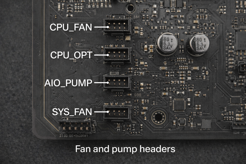
Fan and pump headers (CPU_FAN, SYS_FAN, AIO_PUMP)
Fan headers power and control cooling devices. CPU_FAN must connect for safe boot, while AIO_PUMP headers deliver constant power for liquid cooling.
RGB and ARGB headers
RGB headers use 12V, while ARGB headers use 5V. Mixing them damages lighting hardware instantly, so correct matching matters.
Common motherboard connector mistakes to avoid
Users often confuse RGB headers, skip CPU power connectors, or misplace RAM sticks. These mistakes cause boot failures, lighting damage, or poor performance.
Checking labels and manuals prevents these issues.
How to identify motherboard connectors on your specific board
Motherboard manuals show labeled diagrams for every connector. Printed labels on the board itself also help identify headers during installation.
Manufacturer support pages often include zoomable diagrams.
Motherboard connectors quick reference table
| Connector | Location | Purpose | Power / speed | Common use case |
|---|---|---|---|---|
| 24-pin ATX power | Internal | Powers the motherboard | 12V main power | Required for system startup |
| CPU EPS (4+4 / 8-pin) | Internal | Powers the processor | 12V CPU power | Required for stable CPU operation |
| PCIe x16 slot | Internal | High-bandwidth expansion | PCIe 3.0–5.0 | Graphics cards and capture cards |
| M.2 slot (NVMe) | Internal | High-speed storage | Up to PCIe 5.0 | NVMe SSDs for OS and games |
| SATA ports | Internal | Traditional storage | Up to 6 Gb/s | HDDs and SATA SSDs |
| RAM slots (DIMM) | Internal | System memory | DDR4 or DDR5 | Install system RAM modules |
| USB rear ports | Rear I/O | External device connection | USB 2.0–USB4 | Keyboards, mice, drives, peripherals |
| Front panel header | Internal | Case controls and LEDs | Low voltage signal | Power button, reset, status lights |
| USB internal header | Internal | Front USB ports | USB 2.0–USB 3.x | Case front USB-A or USB-C |
| CPU_FAN / SYS_FAN | Internal | Cooling control | 12V PWM/DC | CPU and case fans |
| RGB / ARGB headers | Internal | Lighting control | 12V RGB or 5V ARGB | Case and component lighting |
| HDMI / DisplayPort | Rear I/O | Video output | Varies by standard | Monitors using integrated graphics |
| Ethernet (LAN) | Rear I/O | Wired networking | 1Gb–10Gb | Internet and local network access |
FAQs about motherboard connectors
What connectors are required for a motherboard to work?
You must connect the 24-pin ATX power connector and the CPU EPS power connector. Without these, the motherboard will not boot.
Do motherboard video ports work with a graphics card installed?
No, motherboard HDMI or DisplayPort outputs usually disable once you install a dedicated GPU. Use the ports on the graphics card instead.
What happens if I plug RGB into the wrong header?
Plugging a 5V ARGB device into a 12V RGB header can permanently damage the lighting hardware. Always match voltage labels before connecting.
Are all M.2 slots the same on a motherboard?
No, some M.2 slots support NVMe only, while others support SATA or share bandwidth with SATA ports. Check the manual to avoid disabled drives.
Summary
- Motherboards include external ports and internal headers with distinct roles.
- Power, storage, and cooling connectors matter most during a build.
- Modern boards add USB-C, NVMe, and advanced cooling headers.
- Manuals and labels prevent wiring mistakes.
Understanding motherboard connectors simplifies PC building, improves upgrade decisions, and protects your hardware as standards continue to evolve.

Discussion (0)
Be the first to comment.